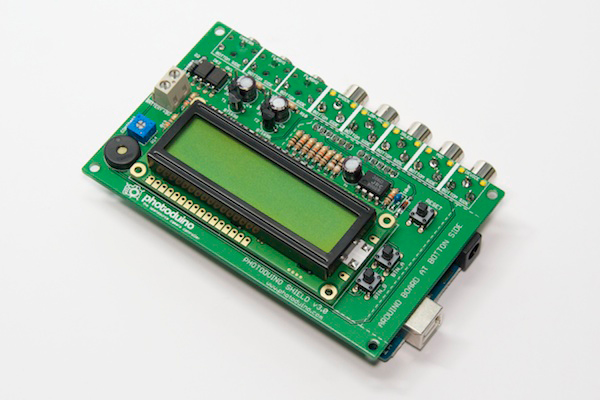
Build instructions: The shield
The first thing so we will start to assemble Photoduino is the shield. You need the components of course, but also you need some tools like soldering iron, tin, cutting pliers and a pair of screwdrivers (with flat and star tips).
IS VERY IMPORTANT know how to soldering well.
Get this comic for easy learning “Soldering is Easy”
The PCB
You should pay attention to the pictures to not make mistakes on those parts that have polarity to respect when soldering.
In addition, some components must be welded to the upper side and positioning in the bottom side (we will start with this parts), so do not miss any detail.
Although this tutorial will explain each component and illustrates his position on the PCB, most of them are shown in the PCB itself.
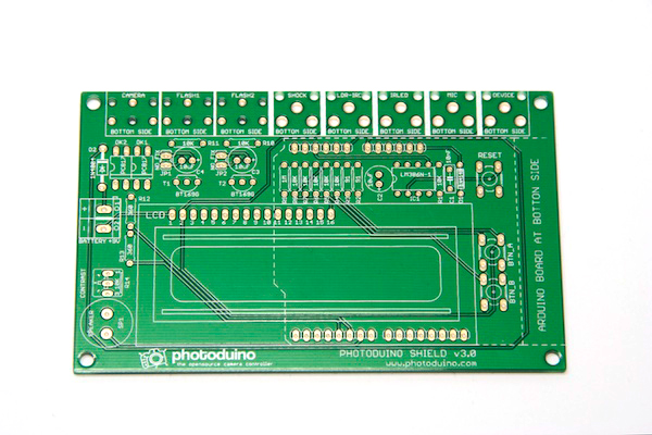
In the next picture you can see which is the upper side of the PCB.
Pins for connecting Arduino
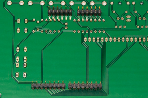
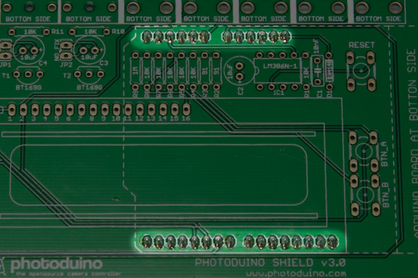
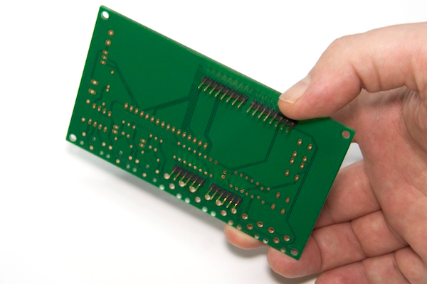
The first thing to solder is the pin headers to connect to Arduino board that will go under the shield. In the next photo you can see the 4 groups of pins. There are two groups of 6 pins and two groups of 8 pins. You put in the bottom of the PCB and then solder from the top of the PCB.
Look closely, are welded to the upper side but are placed at the bottom.
Connectors for sensors, camera and flashes
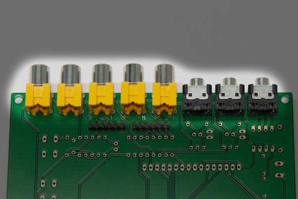
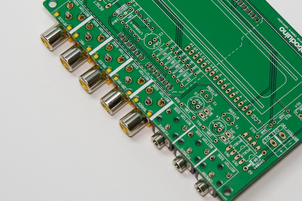
RCA and Jack connectors that go in the PCB, you should also put on the bottom side of the PCB and solder on the upper side.
Other components
From now all components will be placed on the upper side and soldered at the bottom side. The order to follow to solder the parts is based on the height of each component from smallest to largest. This allows to work better when you place a component and turn the PCB to solder on a flat surface like a table, for not having higher components falling when you are soldering.
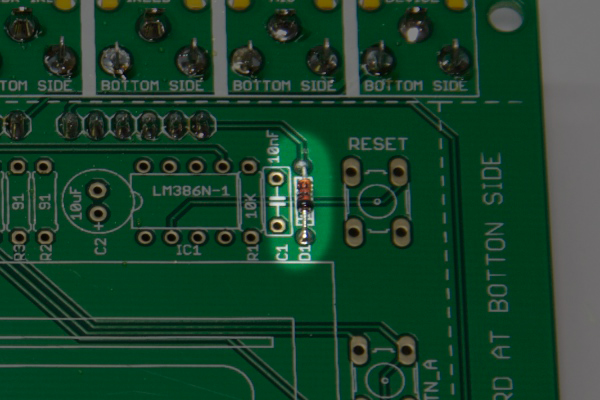
Diode 1N4148
Put in the position you see in the picture below as “D1″. Note that there is a black band on one side of the component to respect the polarity. If you will go to connect this shield to an Arduino UNO R3 board, no need to use this component.
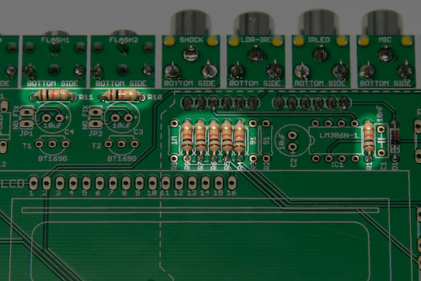
10K resistors
The eight 10K resistors can recognize them by the colors: Brown, black and orange. You must put at positions R1, R4, R5, R6, R7, R8, R10 and R11 as you see in the picture below.
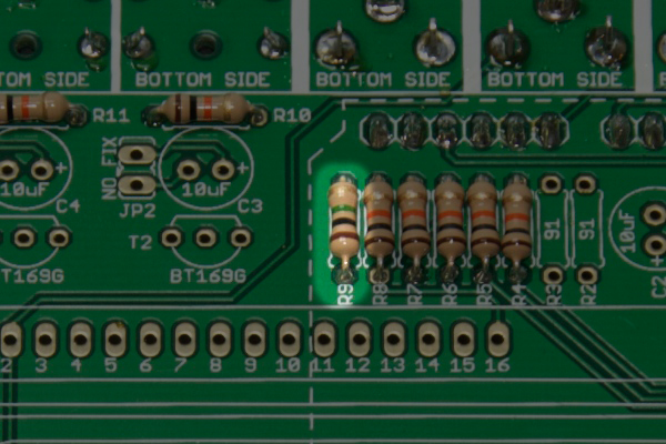
1M resistor
There is only one 1M resistor and its colors are brown, black and green. Put at R9 position.
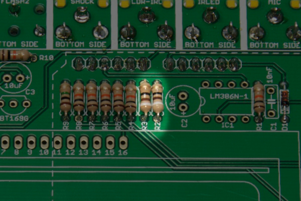
91 Ohms resistors
There are two 91 Ohms resistors with colors white, brown and black to put in positions R2 and R3.
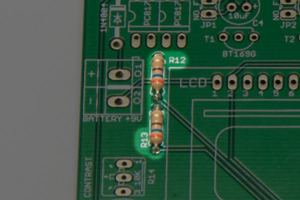
360 Omhs resistors
There are two 360 Ohms resistors with colors orange, blue and brown to put in positions R12 and R13.
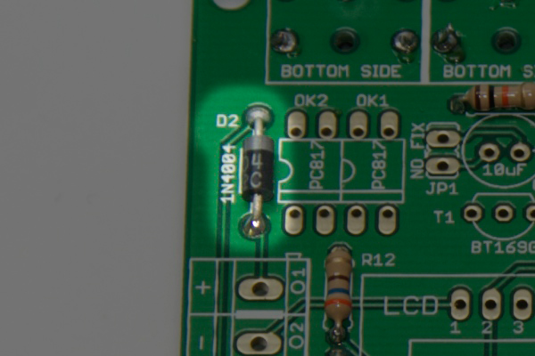
1N4004 Diode
The 1N4004 diode should be placed in position D2, has a gray band at one end to indicate their polarity. You place it as shown in the next picture.
PC817 Optocouplers
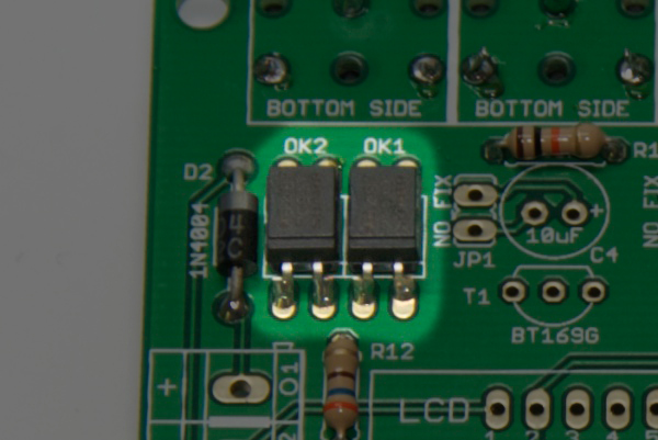
Both PC817 optocouplers you soldering at OK1 and OK2 positions. As you can see in the image below, polarity is indicated by a small relief in one end, which should be placed as in the image below.
LM386 Amplifier
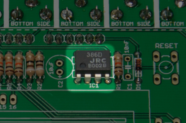
The LM386 amplifier or also JRC386D (depending on brand) you must solder at IC1 place and its correct position you can see in the picture below. The indicator is a small circle relief on the chip.
Speaker
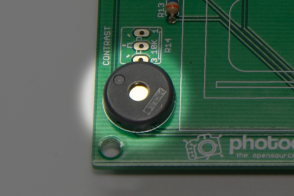
Solder the small speaker in the position indicated as SP1. It has no polarity.
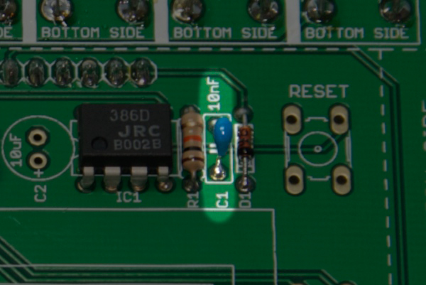
10nF Capacitor
The small 10nF capacitor can be blue as in the picture below or also yellow or brown according to the manufacturer and the material with which is made. You must solder in the position indicated as C1. It has no polarity.
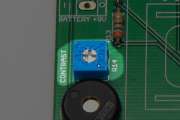
Contrast potentiometer
The 10k potentiometer which you will use to adjust the display contrast, you must solder in the position indicated as R14. It has no polarity.
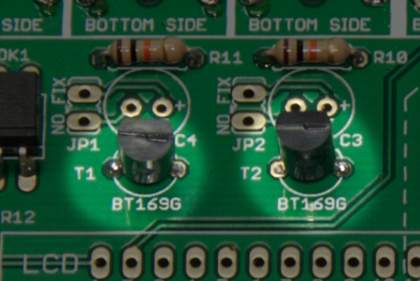
BT169G Thyristors
The two thyristors you must solder in the positions indicated as T1 and T2. Its polarity is indicated by the shape of the thyristor seen from above, which has a flat side and a curved side. You must put it like the picture below (the PCB silkscreen also indicates the correct position).
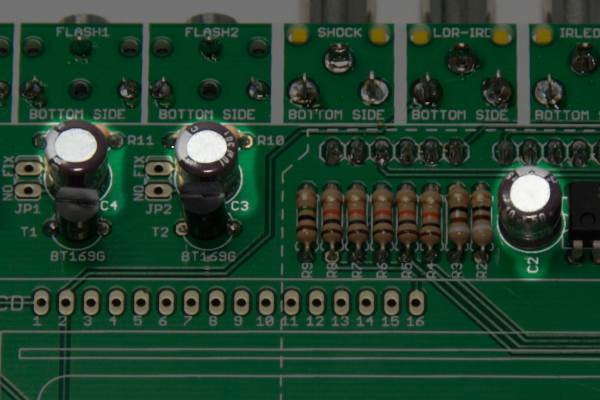
10uF Capacitor
The three electrolytic capacitors of 10uF are in the positions C2, C3 and C4. Its polarity is indicated by a gray band in one side of the cylinder. This band indicates the negative (-) and the silkscreen in the PCB marks which is the positive (+). The easiest way to solder correctly is to look at the next image to see the right position.
Reset and control buttons
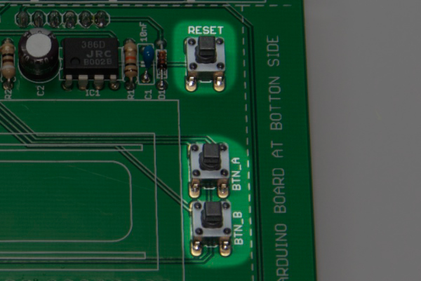
Place the three buttons in the positions indicated as RESET, BTN_A and BTN_B. They has no polarity, but only can be placed in one position.
Battery connector
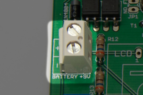
In the next picture you can see how solder terminal connection for external battery.
Flash setting jumpers
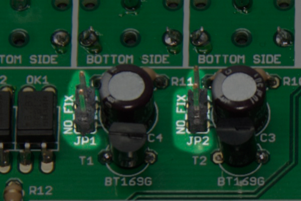
Some very specific flashes may need to activate or deactivate a fraction of the output circuit to function properly. In the next photo you can see that you must put two pinheaders of two ways for put a jumper later.
LCD Display
To solder the LCD to the PCB you must first solder a row of 16 pins to the LCD. Some displays like the following picture are able to use the same pins on the top or bottom as needed. If you have this type of display you must solder the pinheader to the top-left row if you’re looking from the front of the display.
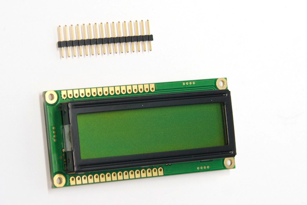
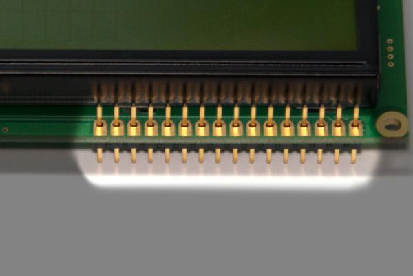
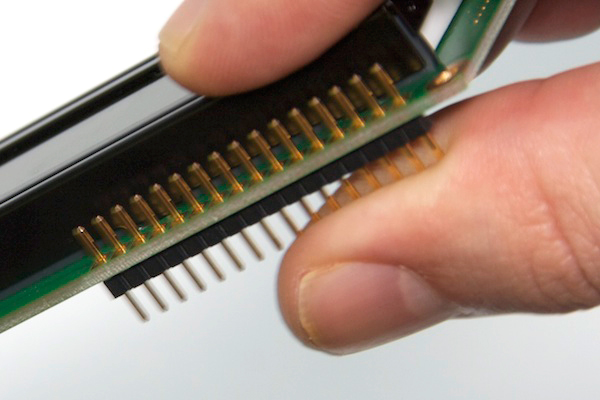
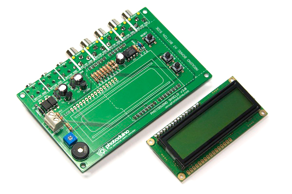
Once the row of pins soldered to the display, you can place the display over the PCB to solder.
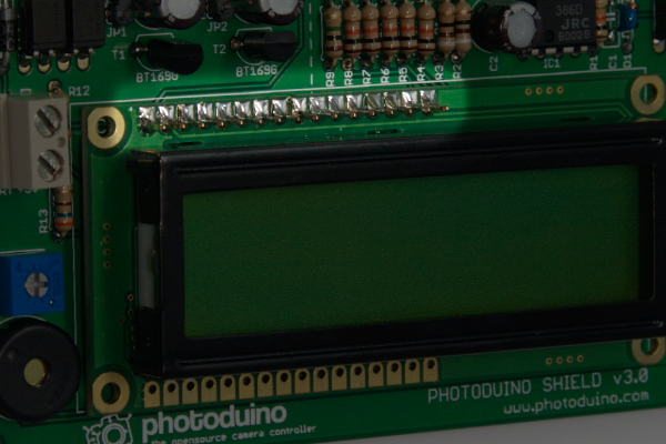
By placing the display on the PCB, you can solder the pins at the other side.
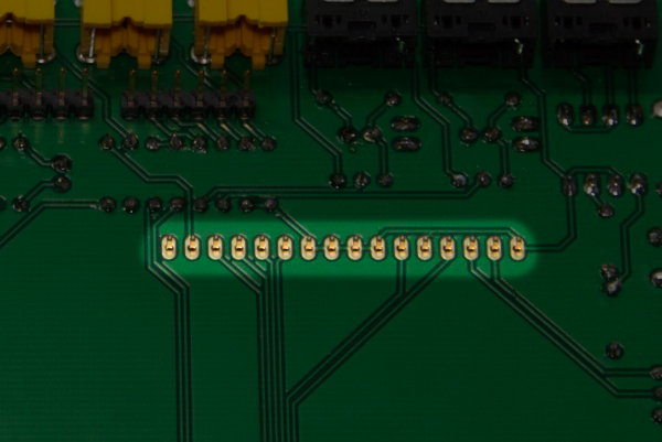
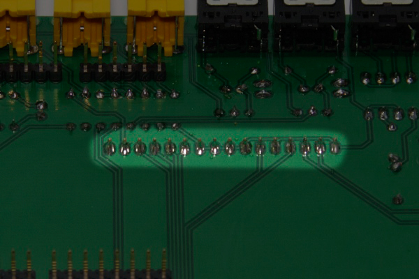
Now you have the shield finished.
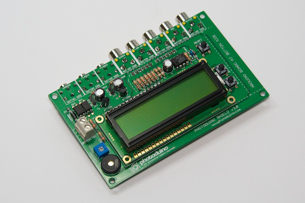
Flash settings
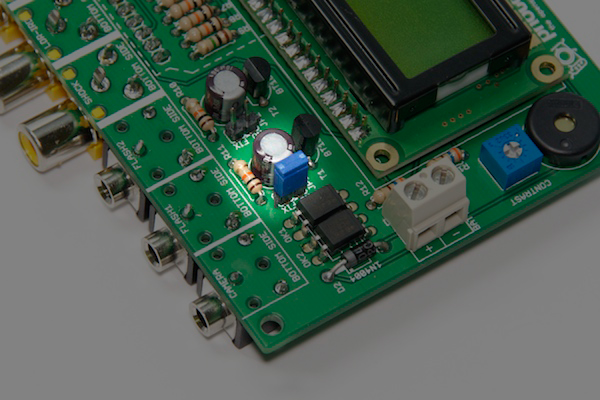
As we mentioned above, some flashes need to activate a small circuit inside the shield to function properly. If you put the blue jumpers as in the picture below, this circuit is disabled, normal for most of the flashes. If your flash model needs the solution, you must remove the jumper to enable the fix at the output of the flash where you go to use it.
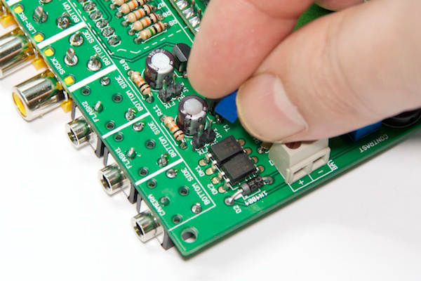
Connecting to Arduino board
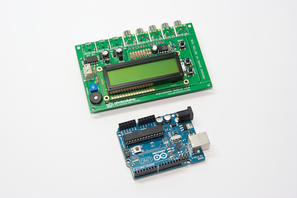
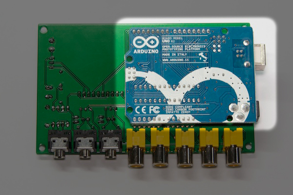
Now that you have fully assembled your PhotoduinoShield 3.0, you only need to add an Arduino board below. You can use any model of Arduino UNO or even an old Arduino Duemilanove.
You have your shield completed ![]()
